

The notion of using the photons emitted from the sun for propulsion in space is not novel. In fact, as early as 1610, Johannes Kepler noticed the potential of this when he pointed out that “comet trails always pointed away from the sun and theorised that the cause may be solar radiation pressure”. Our previous article provided a brief overview and introduction to solar sailing as well as the controlling mechanisms of sailcrafts. In this article, we investigate the deployment of a spinning solar sail with an understanding of both the theoretical dynamics and practical aspects thereof which forms the focus of the original research listed below.
- The categories of sailcraft: spin and three-axis stabilised
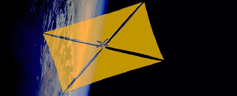
- Sail structures and deployment
- Cubesat solar sail 3-axis stabilization using panel translation and magnetic torquing
- Conclusion
Within the last decade, solar sailing has firmly established itself in reality. Several spacecraft have used solar sailing as a primary means of generating thrust, without the need for propellant, both in Low Earth Orbit (LEO) and interplanetary space. However, the useful effect of a solar sail largely depends on the size of the sail and the mass of the spacecraft. In terms of the former, sailcraft can be divided into two distinct categories: spin and three-axis stabilised.
1. The categories of sailcraft: spin and three-axis stabilised
To control a satellite, it is necessary for both its attitude and orbit to be dynamically stable. Stability can be achieved through the implementation of either three-axis control or spin stabilisation. Three-axis stabilised satellites have “minimal to zero rate of spin and, achieve stabilisation by tightly controlling rates in all three axes of rotation”. These satellites can attain relatively rapid attitude changes in any axis yet are more sensitive to disturbances. Spin stabilised crafts have a large angular momentum which provides stability and disturbance rejection. However, as a result of this significant angular momentum, attitude changes not only require more energy but are also slower. Three-axis stabilised sailcraft require stiff, rigid booms to keep tension in the sail to prevent it from collapsing. If the boom materials are not perfectly rigid, the rates of attitude adjustments should be limited to prevent buckling of the booms due to their own inertia and as a result of the substantial size of these structures. Non-spinning craft are well suited to applications requiring exact pointing ability, for instance, optical or earth observation payloads.
The use of spin stabilised craft, on the other hand, removes the requirement that the booms of the sail be rigid. In this scenario, the centrifugal force generated by the spinning motion can keep the booms and sail in place when deployed thereby reducing billowing and other inconsistencies in the sail surface. And, since the stiffness of the booms is no longer an issue, sails of much larger sizes can be deployed. This does, however, complicate the control of the satellite, and renders spin stable spacecraft unsuitable for certain payloads. The greatest disturbance torque experienced by a sailcraft is the Centre of Mass (CoM) to Centre of Pressure (CoP) offset. This disturbance is averaged out throughout one rotation, which is a significant advantage of spin stabilisation over the three-axis variant.
2 Sail structures and deployment
The construction of a solar sail is multi-faceted and involves disciplines ranging from material science, structural dynamics, to advanced manufacturing techniques and origami. Some of the key areas considered in the design of a sail as a system are sail shapes, boom construction, sail membrane materials and sail folding. To further explain this, a Cubesat mission is discussed in the next section.

3 Cubesat solar sail 3-axis stabilisation using panel translation and magnetic torqueing
A Cubesat mission with a deployable solar sail of 5 meters by 5 meters in a sun-synchronous LEO can demonstrate solar sailing using active attitude stabilisation of the sail panel. To minimise aerodynamic drag and optimise the orbit inclination change caused by the solar pressure force normal to the sail surface, the sail panel is kept parallel to the orbital plane. The practical control system uses a combination of small 2-dimensional translation of the sail panel and 3-axis magnetic torquing that to have sufficient control authority over the gravity gradient and aerodynamic disturbance torques. Miniaturised CMOS cameras are used as sun and nadir vector attitude sensors and a robust Kalman filter is used to accurately estimate the inertially referenced body rates from only the sun vector measurements. This is demonstrated using “realistic simulation tests that the proposed control system, although inactive during an eclipse, will be able to stabilise the sail panel to within ± 2° in all attitude angles during the sunlit part of the orbit, when solar sailing is possible”.

4 Conclusion
A spinning solar sail satellite configuration can rapidly change the solar thrust vector direction during orbit manoeuvres to increase and decrease the orbit altitude in a low earth orbit. However, the deployment and control methods discussed in this article are not limited to spinning solar sails but can be applied to other non-rigid deployable spinning structures as well. These include boom antenna systems, deployable parabolic antennas and large solar panels.
You can find the original research here:
- https://scholar.sun.ac.za/handle/10019.1/98477
- WH Steyn and V Lappas “Cubesat Solar Sail 3-Axis Stabilization using Panel Translation and Magnetic Torquing” (2011) 15(6) Aerospace science and technology 476-485 (available at https://www.sciencedirect.com/science/article/abs/pii/S1270963810001331).
- WH Steyn and HW Jordaan “An active attitude control system for a drag sail satellite” (2016) 128 Acta Astronautica 313-321 (available at https://www.sciencedirect.com/science/article/abs/pii/S0094576516300819).
- Solar Sailing Translation Stage Demo available at https://youtu.be/TO_1WWHpAc8